Why Are Larger PV Modules More Fragile?—Analyzing the Mechanical Strength Crisis and Industry Concerns

Lead-in

As module sizes increase, material usage has not risen but instead decreased, leading to high breakage rates in projects. How did this happen, and what hidden information lies behind it?


Table of Contents:
Chapter 1: A Startling Revelation
Chapter 2: Fragile Glass
Chapter 3: Single Testing
Chapter 4: Path to Solutions


Chapter 1: A Startling Revelation

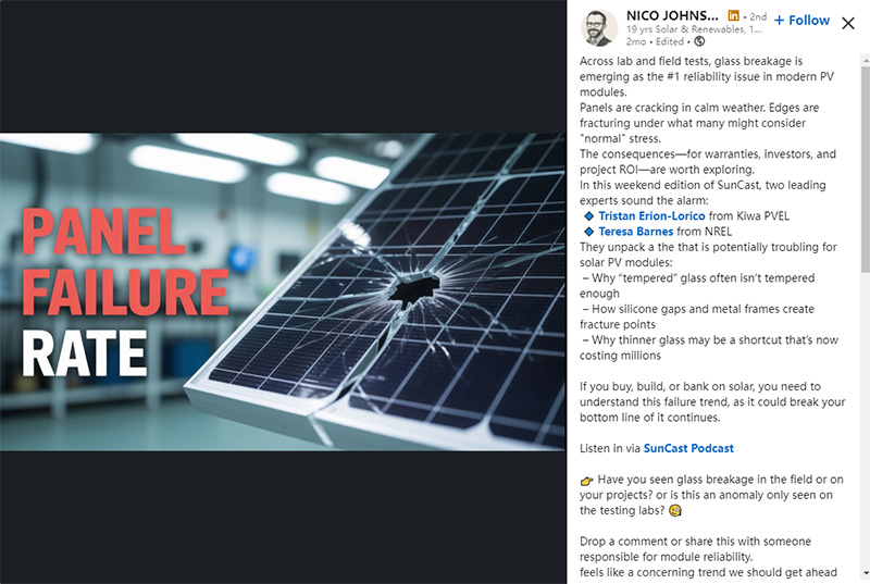
On October 20, 2025, the renewable energy podcast channel SunCast posted on LinkedIn, citing test results from independent third-party Kiwa PVEL, revealing a shocking phenomenon.


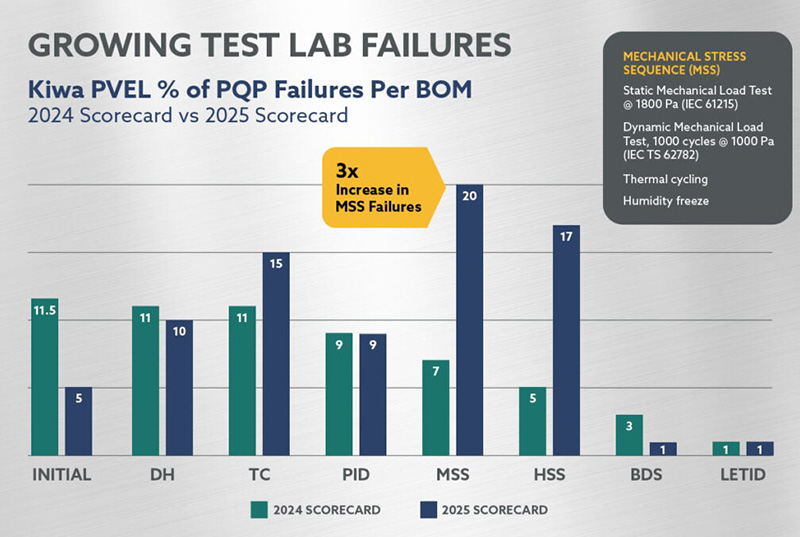
Kiwa conducted mechanical load tests on a large number of modules this year, with 20% failing under a static pressure of 1800 Pa. In contrast, the failure rate in 2024 was only 7%.
#photovoltaic module solar

▽ A linkedin post on the SunCast podcast


This post quickly gained traction on LinkedIn, sparking debates in the comments section over the validity of the 20% failure rate. However, as more third-party institutions joined the discussion, it became clear that high module breakage rates are widely recognized in the industry.
#photovoltaic module solar

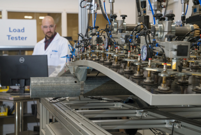
▽ Mechanical load testing at Kiwa Laboratory


In fact, as early as June this year, Kiwa invited 50 module manufacturers for a comprehensive "health check" of their products. Kiwa also innovatively introduced a "Reliability Scorecard" system to help users accurately assess the performance of different manufacturers’ modules.


The tests were strictly conducted in accordance with IEC 61215 standards, covering static load, dynamic load, hail resistance, and electrical performance. The results showed frequent occurrences of glass breakage, frame tearing, junction box damage, and other issues, with an overall high damage rate of 20%.
#solar photovoltaic system

▽ MSS(Mechanical Stress Sequence)

The failure rate of mechanical loads is three times that of previous years


Kiwa’s mechanical load test sequence includes various installation methods, identified by numbers:

  1. 400mm mounting holes, ±1800 Pa static pressure test
  2. 790mm mounting holes, ±1800 Pa static pressure test
  3. Four-corner mounting along the short edge, ±1800 Pa static pressure test
  4. Dual-rail four-clamp mounting, ±2400 Pa static pressure test


Clearly, these tests are ranked from highest to lowest in terms of mechanical performance requirements. Kiwa uses this numbering system to track which modules pass which tests, allowing users to indirectly judge the mechanical strength of the modules.


Apart from Kiwa, other third-party institutions worldwide have also noted the widespread issue of module breakage in recent years.


In 2022, FUSC (Federal University of Santa Clara) established a 100 kW experimental site in southern Brazil, equipped with bifacial modules on trackers. Within a year, 83 out of 158 modules developed glass cracks, a breakage rate of 52.5%.


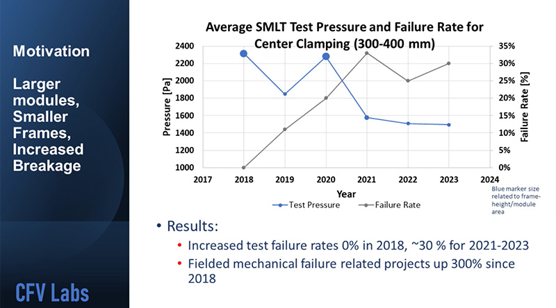
In 2023, CFV Laboratory mentioned in an online exchange that their test data showed module failure rates in 2023 were three times higher than in 2018. Nearly 30% of the modules tested by CFV failed under a test pressure of 1500 Pa.
#solar photovoltaic system

▽ The pressure resistance of components is decreasing year by year

The failure rate of components is increasing year by year


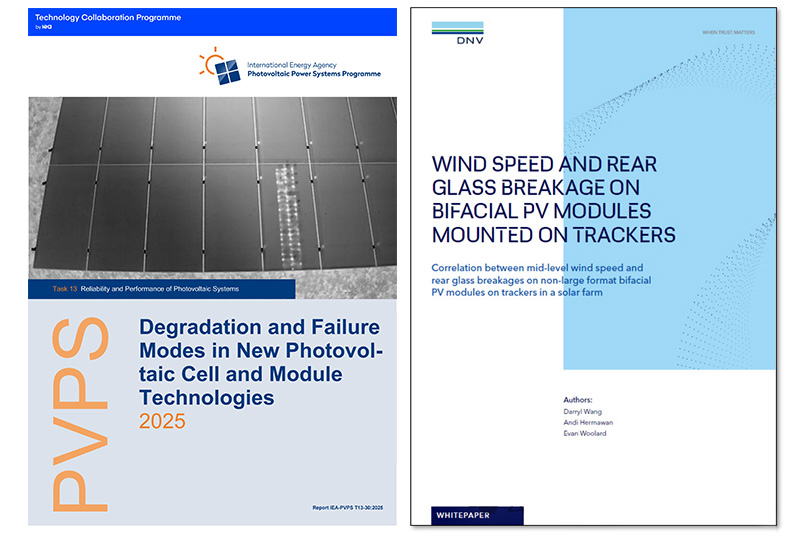
In 2024, DNV published a white paper claiming that in a bifacial module tracker project in the Asia-Pacific region, 15% of the modules’ rear glass broke when wind speeds exceeded 15 m/s.


In February 2025, the IEA PVPS task force released a report on module failure rates, stating that bifacial modules with 2 mm glass could experience rear glass breakage rates of 5–10% within the first two years of installation.
#photovoltaic module solar

▽ Reports on component damage by PVPS and DNV


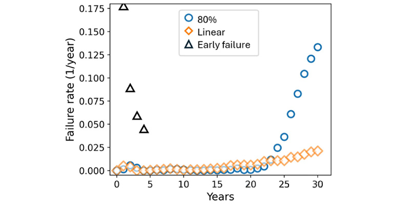
In March 2025, IEEE magazine published an article analyzing the current glass breakage rates of bifacial modules, noting that the first five years of a project represent the peak period for module breakage, with rates as high as 17.5%.
#photovoltaic module solar

▽ The failure rate of components published in the IEEE Photovoltaic Journal


It seems as if, overnight, once-durable modules have become fragile, which is disheartening.


Chapter 2: Fragile Glass

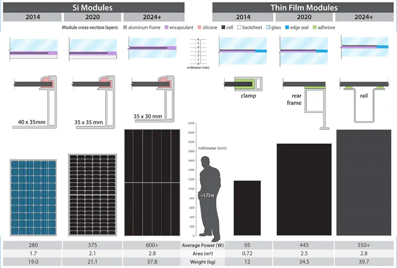
Since the trend toward larger modules began in 2020, module sizes have rapidly increased, meaning each module must withstand greater pressure. However, to make matters worse, material usage for larger modules has not increased but decreased:

• Glass thickness: reduced from 3.5 mm to 2 mm

• Aluminum frame height: reduced from 40 mm to 30 mm

• Aluminum frame thickness: reduced from 2 mm to 1.2 mm
#photovoltaic module solar

▽ As the component size increases, the material usage decreases


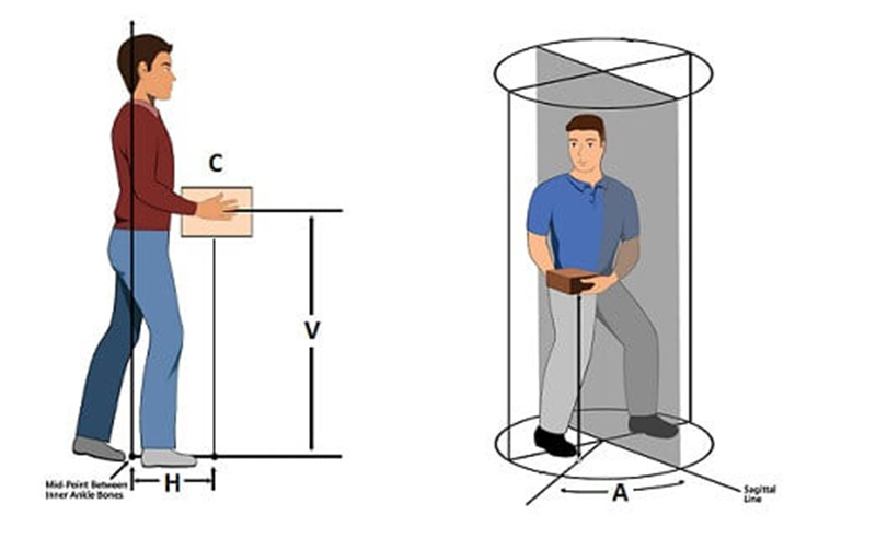
While reducing material usage helps decrease the overall weight of modules, speeding up installation, it also raises concerns. According to the National Institute for Occupational Safety and Health (NIOSH), the maximum recommended weight for two-person lifting every five minutes is 33.5 kg.


Clearly, if material usage from the single-glass module era were maintained, many modules would far exceed this weight limit.
#photovoltaic module solar▽ NIOSH has strict regulations on artificially lifted weights


Of course, it is widely understood that the primary goal of reducing material usage is cost reduction.


However, cost reduction has inadvertently led to lower quality control. The complexity of producing 2 mm glass is nearing the ceiling of glass manufacturing technology, making quality control far more challenging than for 3.2 mm glass.


To enhance shatter resistance, PV module glass often undergoes thermal and chemical treatments. The strength of the glass largely depends on this treated, reinforced surface layer, which typically accounts for 40% of the glass thickness.


During the 3.2 mm era, manufacturing processes could effectively create this protective layer. However, maintaining the same protective layer thickness in the 2 mm era has become exceptionally difficult.
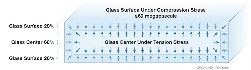
#photovoltaic module solar▽ The protective layer on the surface of the component generally accounts for 40% of the total thickness


Now, the breakage patterns of thick and thin glass in the field have fundamentally changed. Previously, 3.2 mm glass breakage often appeared as "center cracking," making it easier to trace the failure point. In contrast, 2 mm glass failure cracks appear randomly, making it extremely difficult to identify the cause of failure.
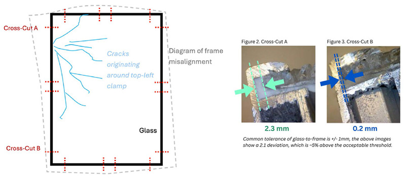
#photovoltaic module solar

▽ The differences in the production process of component frames also affect the mechanical properties of the components


This complicates the implementation of effective corrective measures when modules are damaged. Even if modules are replaced, similar damage may recur.
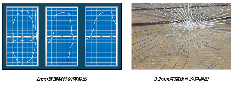
#PV modules

▽ The situation of component glass shattering has changed


Chapter 3: Single Testing

Behind the phenomenon of module breakage at project sites, another critical factor cannot be ignored. When module manufacturers specify mechanical performance, they often rely on the test requirements of the IEC 61215 standard. IEC provides a comprehensive testing protocol and specifies a test safety factor: r_m = 1.5.


This cave once wrote a special article titled "Test Loads & Design Loads: How to Match Project Requirements?" The significance of this safety factor is also discussed in the text. The safety factors of glass produced by different processes are also not the same.
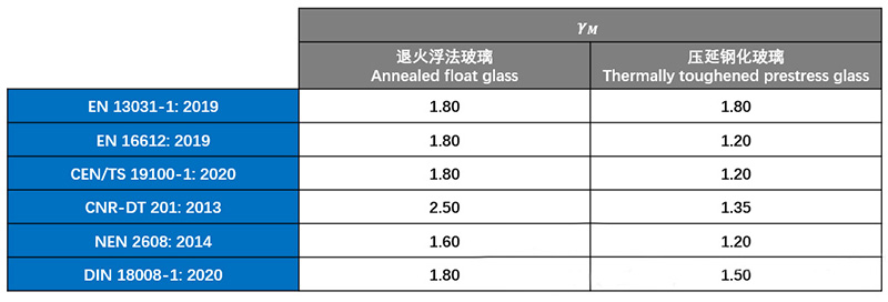
#PV modules

▽ The safety factors of different process glasses


This safety factor’s significance varies depending on the glass production process.Due to the inherent randomness and inconsistency in float glass production, the required safety margin is generally higher than for rolled glass. Currently, module manufacturers often opt for cheaper float glass for the rear glass of modules. As shown in the table, the safety factor for annealed float glass ranges from 1.6 to 2.5.


Thus, for material property safety margins, the 1.5 safety factor required by IEC is clearly insufficient.


But this is not the most alarming issue.


When designing projects, a module compatibility test is often conducted to determine whether a specific module matches the tracker structure. This test applies the project’s required loads to the module based on the actual tracker and module installation method. Passing this test is used to verify that the module meets project requirements.


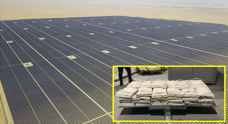
At first glance, this process seems logical and compliant. However, it overlooks a critical issue: all tests are conducted only once. Whether for small kW-scale projects or large GW-scale projects, the reliability of millions of modules in a power plant hinges on a single sandbag test.
#PV modules

▽ The fate of the entire photovoltaic power station lies in a single component test


It is important to note that even for modules of the same model, structural characteristics can vary due to different production batches. This means each module is unique, and testing a single module cannot comprehensively and accurately reflect the true condition of all modules.


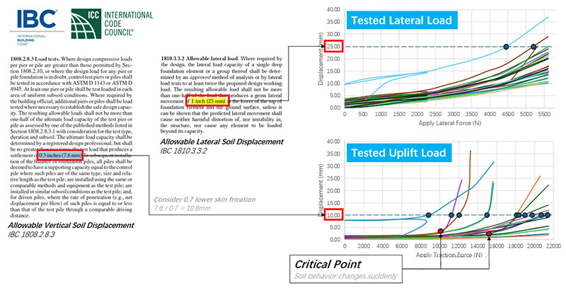
Module load testing is similar to structural testing. In the structural industry, obtaining accurate structural characteristics typically requires extensive repetitive destructive testing (test-to-failure). This approach accumulates reliable data to form a stable sample.
#PV modules

▽ For instance, in POT testing, multiple samples are often required and the failure limit is repeatedly measured


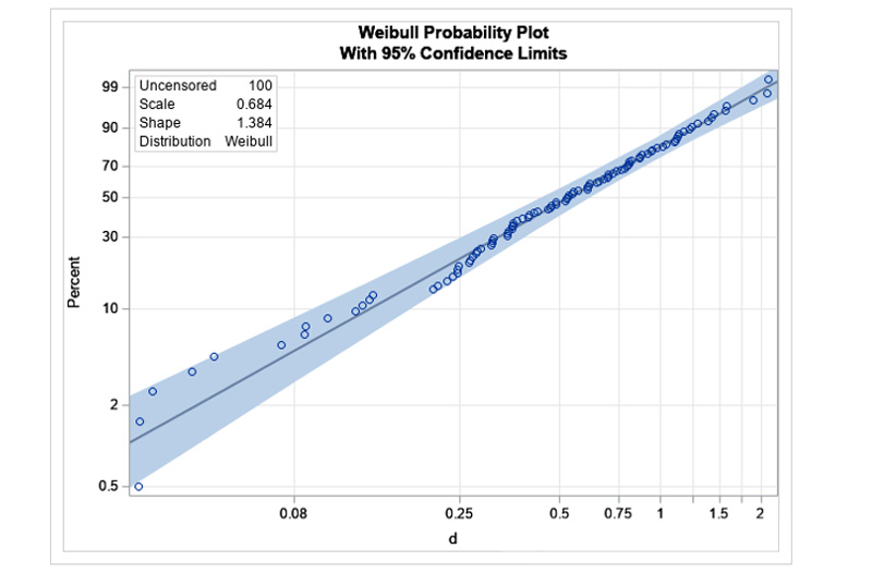
It is worth noting that such destructive testing requires a specific sample size, usually 25–50 modules per sample group. Based on this large sample data, a Weibull probability distribution model can be constructed, and statistical analysis can derive the coefficient of variation. Finally, this coefficient of variation can be used to calculate the safety factor corresponding to material uncertainty.
#PV modules

▽ In statistics, the Weibull distribution is often used to determine the probability of product failure


Chapter 4: Path to Solutions

This article focuses on the long-term trend in the PV industry: cost reduction and efficiency improvement. Cost reduction is not limited to modules; under immense cost pressures, other system equipment is also exploring optimal cost-reduction paths. However, when various equipment manufacturers’ "new technologies" are applied at the system level, they inadvertently increase the risk of module breakage.


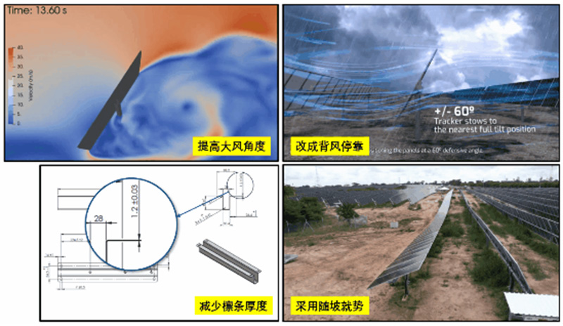
Common cost-reduction measures for tracker manufacturers include:

• Increasing the stow angle from 30° to 60°

• Reducing purlin thickness from 2 mm to 1.2 mm

• Increasing column spacing from 7 m to 10 m

• Switching from windward stowing to leeward stowing

• Adapting to terrain by bending the main shaft and modules to reduce earthwork


Due to industry barriers, collaboration between module and tracker manufacturers is challenging. The result is each party reducing its own costs while shifting the ultimate risk to system users.
#PV modules

▽ Trackers are also adopting various "new technologies" to reduce costs


However, not everyone chooses to "bury their head in the sand." Increasingly, people are actively exploring solutions and proposing various creative ideas.
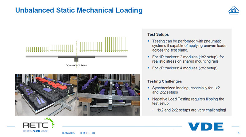
#PV modules

▽ VDE proposes unbalanced component testing
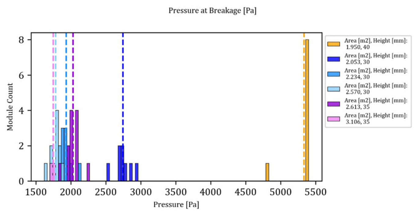
 

#photovoltaic module solar


▽ Steel frames can effectively enhance the pressure resistance capacity of components
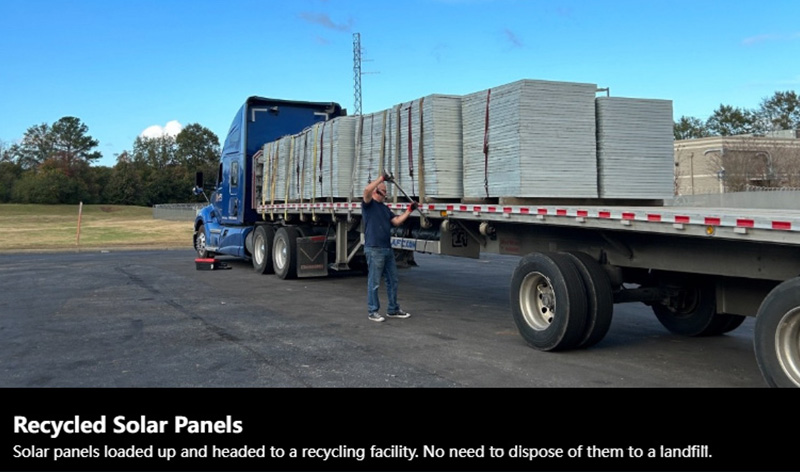
 

#Component recycling

▽ The component recycling industry has also quietly emerged
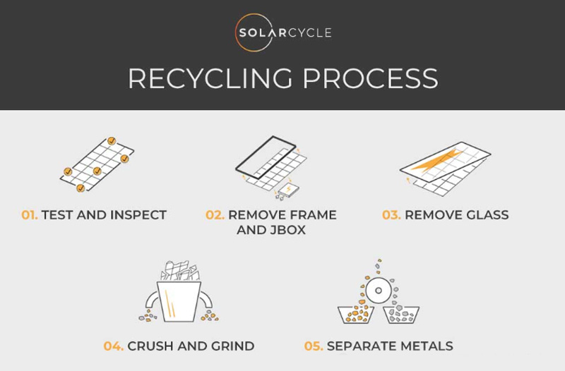
 

#Component recycling

▽ The general process of component recycling


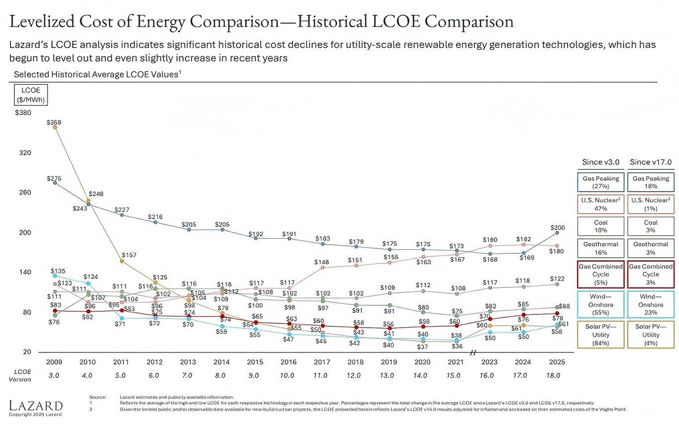
In 2025, thanks to collective efforts, the cost of PV power generation has reached a historic low. Among various power generation methods, PV has become the undisputed leader in LCOE (Levelized Cost of Electricity).
#photovoltaic module solar

▽ Photovoltaic power has become the most cost-effective energy source for power generation


This achievement is inseparable from every individual reading this article. Let us work together to break industry barriers, face challenges, and embrace greater opportunities of the era.
 

Top

Top 10 Solar Mounting Manufacturer Provide Solutions for Tilt Roof |Artsign

Artsign design variety of solar tilt mount, we offer a wide variety of solutions for tilt roofs–tile roofs, metal roofs, slate roofs…… We strive to provide the best solution to meet the needs of every client.
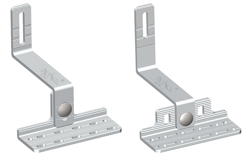
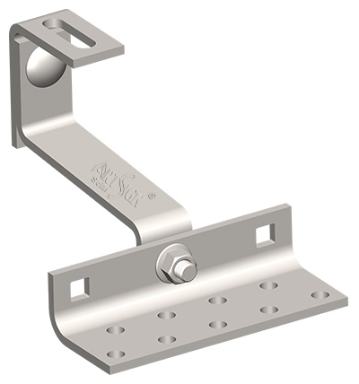
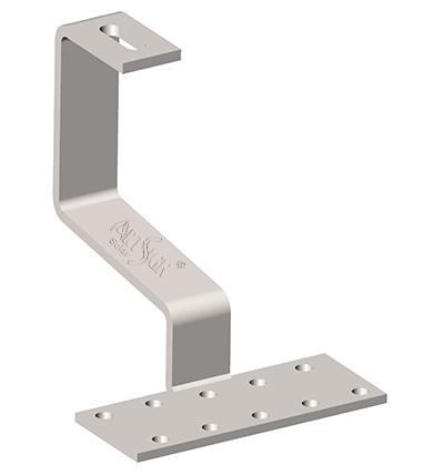
For tile roofs, Artsign has designed a variety of stainless-steel hooks that can be used without damaging the roof structure. These hooks are directly fixed to the wooden beams with screws and then connected to the rail.


We offer both adjustable and non-adjustable stainless-steel hooks to meet the needs of different customers.

solar adjustable hooks

Artsign offers various adjustable hooks, such as the AS-RH-12 model, to accommodate different tile thicknesses, rafter spacings, and roof unevenness. The adjustable mechanism avoids stress points on the tiles, reducing pressure and eliminating the need for forceful tile pressing to align with the guide rail.
This is very user-friendly for installers, reducing labor time; for contractors, it means lower labor costs; the adjustable hooks make it easier to straighten the guide rail, improving the homeowner's experience; and for suppliers/distributors, it reduces inventory pressure and lowers the risk of incorrect shipments.
In addition, we also offer fixed hooks. These fixed hooks feature a one-piece structure without adjustment holes or grooves, allowing for more direct stress over time, lower cost, and higher cost-effectiveness.

stainless steel hooks


To meet the needs of different materials, we also offer stainless steel hooks made of aluminum. Aluminum roof hooks offer lighter weight, better system compatibility with aluminum rails, lower cost, and sufficient corrosion resistance for most residential PV installations.

solar brackets for tile roof

These are all solar brackets for tile roof.
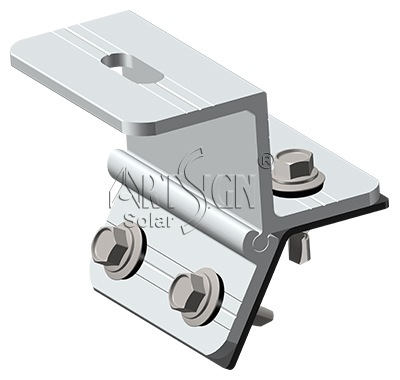
Artsign designs a wide variety of solar panel mounting system for metal roof. Such as aluminum roof brackets and N clips
We offer two types of aluminum roof brackets: penetrating and non-penetrating.
Penetrating roof brackets have high load-bearing capacity, suitable for strong winds and long spans.


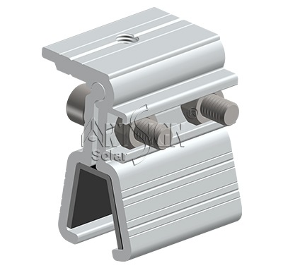
Non-penetrating clamps
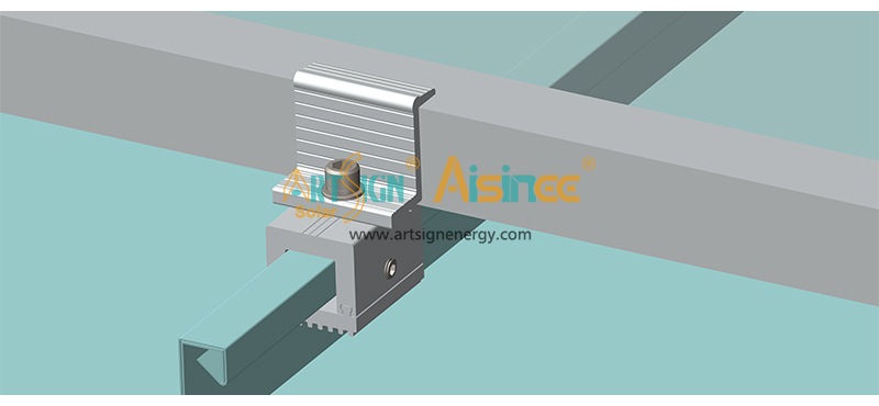
Non-penetrating clamps require no drilling, ensuring roof safety, and are secured by clamping the vertical edges without damaging the roof's waterproofing layer. We have nearly 20 types of non-penetrating clamps, and we will select the most suitable clamp based on the angle of the customer's roof.


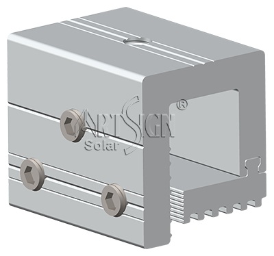
N clips

N clips can be used with L feet and L connector to fix with long rail profiles. It can be directly work with solar mid clamp and end clamp and thus can fix the solar panels directly without any long rail. It’s light for transportation and easy for installation.

solar brackets for slate roof

As we mentioned earlier, Artsign also designed solar brackets for slate roof. The straight stainless-steel hooks effectively solve the problem of secure installation without damaging the roof surface.

solar tilt mount

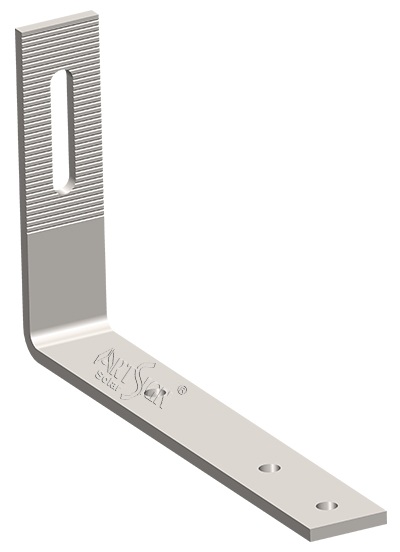
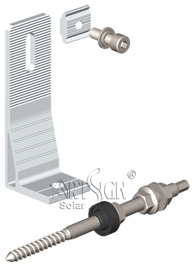
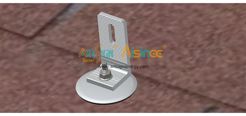
In addition to the solutions mentioned above, we also have a solution that is applicable to all three scenarios and is the most economical—an L Feet with a hanger bolt.

L Feet

This is the most economical solution, requiring the fewest accessories. However, for tile or slate roofs, using hanger bolts damages the roof surface and may result in poor waterproofing.
For any inquiry of solar panel mounting system, pls contact us, E-mail: sales@artsign.net.cn, WhatsApp / WeChat / Skype: +86 18030235875, thanks.


Top

Why has the Mini Rail Roof Mount System become so popular? | Art Sign

The most important issues facing EPC contractors and installers are rooftop space utilization efficiency, installation speed, and overall system costs as the world’s installed solar capacity continually increases. Consequently, throughout Europe, Australia, and certain regions of Latin America, the solar mini rail system has quickly emerged as the top option.


Because of its lightweight form, quick installation, low material requirements, and strong adaptability, mini rail is quickly replacing classic long solar profile systems as the current trend.

Photovoltaic Bracket


Technical Specifications
Product name
Photovoltaic Bracket Mini Rail Solar Mount System
Material
Aluminum 6005-T5
Surface Treatment
Anodized silver above 10 micron
Length
Can be customized
Height
20mm-100mm
Installation
Metal roof,flat roof
Warranty
20 years warranty,25 year service life
Packing
cardboard or wooden box

Less Material = Lower System Cost, Smarter Roof Solutions
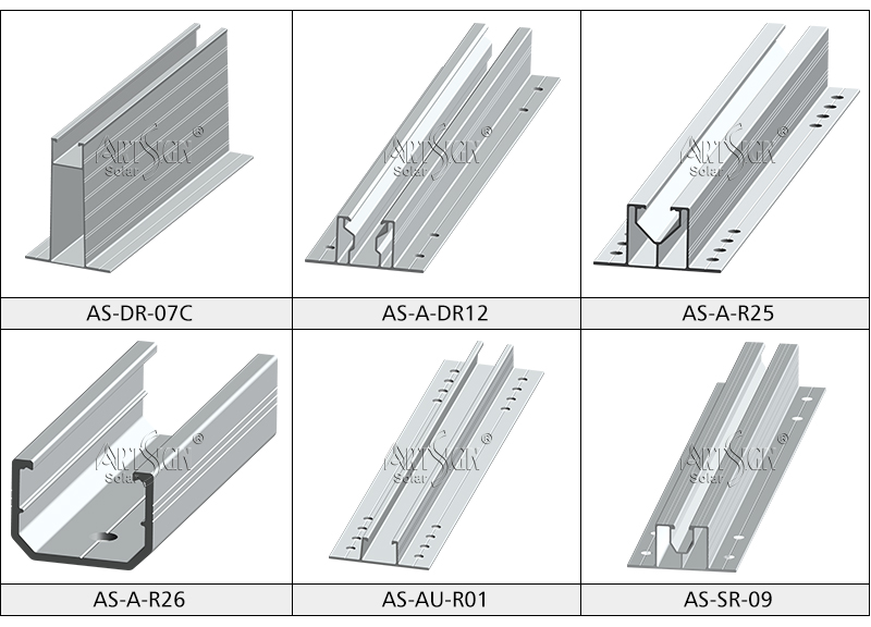
Mini rails are shorter than normal rails, which are usually 2 to 4 meters long. Most additional accessories, such as rail transport equipment and rail splices, are reduced. This not only greatly reduce the material need, but it also minimizes the volume and weight of transportation, saving logistics money.
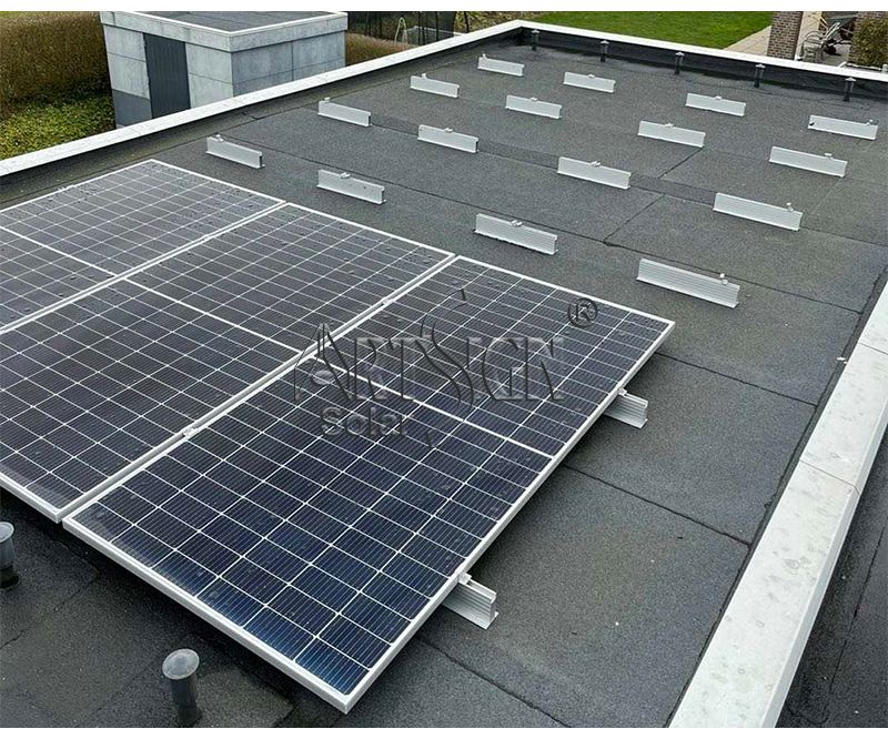
The mini rails are more flexible, is suitable for oddly shaped roofs or limited spaces solar pv flat roof. There is no need for extra cutting, which increases installation efficiency and reduces labor costs.
Also, due to its lightweight design, it is very suitable for lightweight steel roof structures, which further improves the system's safety and applicability.


Speed-Optimized Design = Install More Roofs in the Same Day
ArtSign's Mini rail series is usually pre-cut at the factory, with all other accessories pre-assembled, making installation much simpler.
It doesn't require rail splicing, measuring, or alignment like normal methods do. Just install the mini rail to the roof, assembling the parts, and locking the Photovoltaic Bracket clamps completes the installation.


Solar Pv Flat Roof


This effective installation solution reduces projects work time by 30 to 50%, which saving lowers labor costs. Because of its efficiency advantage, which is particularly apparent in multi-roof projects, it is the most cost-effective roof structure for solar panel deployment.

Mini Rail is especially suited for residential and commercial and industrial rooftop due to its high efficiency, lightweight structure, and easy installed. It enables installers finish more work in a day, significantly increasing project delivery speed and enhancing overall cost efficiency.


Modular Structure = Wide Compatibility Across Roof Types
The Mini Rail system will suit different roof types and solar module layouts because of its easy installation and adaptable structural design.
The Mini Rail system is suitable for several flat roof designs as standing seam, corrugated, and trapezoidal metal roofing or some cement roof. By adjusting the rail spacing to suited different solar panels sizes, which ensures better layout adaptability and increased compatibility.

To enhance roof sealing performance, ArtSign also offers custom rubber waterproof pads suitable for different Pv Panels On Flat Roof. These ensure safe, reliable, and long-lasting waterproofing advantages even on complex roof structures.


High-Strength Materials = Reliable Performance in High Wind & Snow Loads
ArtSign's premium mini rail system utilizes 6005-T5 aluminum and 304 stainless steel bolts, ensuring a lightweight structure with exceptional mechanical strength.
Before shipment, products must pass multiple strict tests to ensure compliance with product certification standards such as ISO 9001, CE, and TUV. Even with strong winds or heavy snow areas, it continues to stand stably under pressure.

Mini Rail has been in use for over 20 years in Germany, Poland, the Netherlands, Japan, and other developed countries. Because the mini mount system has earned the trust of numerous EPC contractors and installers due to its stability, durability, and longevity.


Future Trends = Low Cost × High Efficiency × Lightweight Structure
As demand for rooftop solar structures continues to grow, the market is turning toward system solutions that are lighter, require less labor, and offer greater overall cost advantages.
Mini Rail is a perfect fit for this trend because of its special design, lightweight, and quick install speed.

In addition to lowering labor and material costs, it greatly speeds up installation efficiency, making workers to finish more roofing projects in the same time.  Because of this, it quickly becoming as the structural option of choice for residential, commercial, and industrial solar installations.


Responding to market trends, ArtSign as a top10 solar mounting system supplier in China, which has designed the Mini Rail system, optimized for global rooftop projects. This system offers huge improvements in structural reliability, installation efficiency, and adaptability to various roof types by utilizing more than 20 years of manufacturing experience and global market knowledge. It enables clients to finish superior projects more quickly and cheaply.
The Mini Rail System from ArtSign is a rooftop solar solution that is ready for the future, not just a mounting system.
Through skilled design, standardized manufacturing, and worldwide experience, we will continue to propel global rooftop solar growth, efficiency, and cost decreases.
For any inquiry of solar panel mounting system, pls contact us, E-mai:sales@artsign.net.cn, Whatsapp / Wechat / Skype:+008618030235875, thanks.


Top

Unlock the Value of Every Square Inch The High-Efficiency, Compact Single-Post Solar Mounting System | ArtSign

In the design of photovoltaic (PV) power plants, we often face a core dilemma: how to safely and stably install more modules within limited land or roof space to maximize power generation revenue? Traditional multi-post layouts can sometimes be constrained by space and cost.


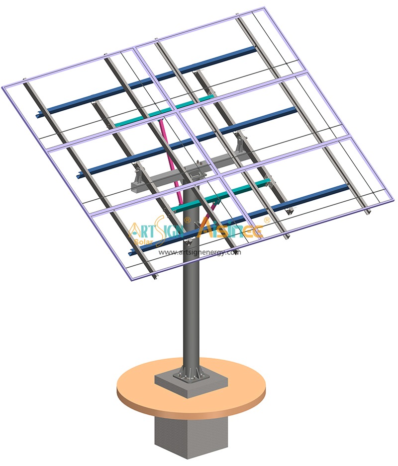
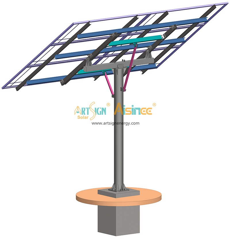
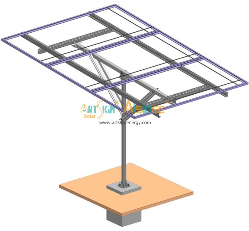
Today, we introduce an innovative solution — the high-efficiency, compact single-post solar mounting system. True to its name, it uses a single central post as the core, supporting a modular array and elevating space utilization and design flexibility to new heights.


single-post solar mounting system


I. Core Advantages: Beyond "Single-Post," It's "Intelligent Integration"
Taking the typical "single-post, 6-panel" design as an example, this system is far from a simple structural simplification; it is the result of deep optimization.


Ultimate Compactness, Saves Space
Compared to traditional dispersed supports, the single-post design significantly reduces the number of foundation or roof contact points. This means within the same available area, you can plan for the installation of more PV modules, markedly increasing the installed capacity and power generation efficiency per unit area—especially valuable for space-constrained commercial and industrial rooftops.


high-density PV racking solution


Adjustable Tilt, Captures Sunlight

As illustrated in product examples (e.g., the 3x2-35deg design), the system's tilt angle can be custom-designed according to the optimal solar angle for the project location (e.g., 35 degrees). This flexibility ensures that, regardless of latitude, the modules can receive solar radiation at a near-ideal orientation, optimizing annual energy yield.


adjustable-tilt single-post solar mount


Modular Design, Flexible Expansion

The "6-panel" setup is an efficient module, but it is not fixed. Our system supports personalized design based on the client's specific needs, site shape, and load-bearing conditions. You can adjust the number of panels supported per post, the arrangement (portrait or landscape), building a solution that fits your site perfectly, like assembling building blocks.


compact solar installation for commercial rooftops


Sturdy and Reliable, Built to Endure

Excellent structural design grants it superior wind resistance (e.g., capable of withstanding 100 km/h winds). Through rigorous mechanical calculations and simulation, the single-post system achieves structural simplicity without compromising the strength and durability required for the power plant's entire lifecycle.


II. Where Can It Be Applied?
This system has a wide range of applications and is particularly adept at creating value in complex scenarios:
Commercial & Industrial Flat Roofs: On roofs with sufficient load-bearing capacity, its compact layout can avoid obstacles like equipment areas and vents, enabling higher-density installation and directly increasing owner revenue.

Agrivoltaics / Aquavoltaics: Single-point support reduces the number of ground piles, minimizing impact on agricultural farming or aquaculture, truly achieving "dual land use, multiplied benefits."


Complex Terrain and Sloped Land: By adjusting post height and foundation type, it can better adapt to uneven ground, reducing large-scale earthworks and lowering initial investment and environmental disturbance.
Choosing a solar mounting system is choosing the "skeleton" and "foundation" of your power plant. Our single-post compact mounting system, with its distinctive features of small footprint, adjustable tilt, and flexible design, offers you a smarter, more efficient foundational solution for your power station. It is not just a product innovation but an evolution in design philosophy—aimed at tailoring the optimal energy harvesting blueprint for every inch of your valuable space.
For any inquiry on solar panel mounting system, please contact us, E-mail: sales@artsign.net.cn, Whatsapp / Wechat / Skype: +0086 180 3023 5875, thank you.


Top

Tailoring the Perfect Fit for Your Roof How to Choose the Optimal Solar Mounting System | Art Sign

When planning a rooftop PV power plant, have you ever wondered why two neighboring factories might have drastically different mounting system designs and initial investments? The key often lies with that “silent guardian” – the solar mounting structure. Choosing the right system is not only the cornerstone of safety but also the first step towards maximizing the economic return on your project.


While owners and investors often focus on the brands of modules and inverters when evaluating a solar quote, the mounting system is frequently overlooked. Yet, this “unassuming” component is fundamental to ensuring 25 years of stable operation for your power station. Today, we will take a deep dive into how to “tailor the perfect fit” for your unique roof, selecting the safest and most economical mounting solution.


I. Flat/Low-Slope Roofs: The Art of Balancing Safety and Cost
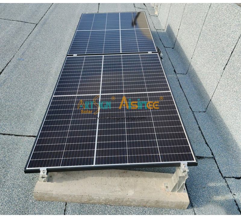
Flat roofs are a mainstream scenario for commercial and industrial distributed solar. Here, the core considerations for choosing a mounting system are wind uplift resistance, waterproofing protection, and load control.
Ballasted Systems (Concrete Blocks):
Advantage: Causes absolutely no damage to the roof waterproofing layer, which is its greatest appeal. Offers flexible installation adaptable to various layouts.
Best For: The vast majority of concrete roofs and steel structure roofs with sufficient load-bearing capacity.
Penetrating/Permanent Fixation (Chemical or Mechanical Anchors):
Advantage: Provides the highest connection strength and excellent wind resistance.

Best For: Areas with extremely high wind resistance requirements, or special reinforcement areas like roof parapets.


 Hybrid Systems


Hybrid Systems:
Combine ballast with point attachments. This approach ensures safety while minimizing impact on the roof surface and is a current mainstream trend.
II. Metal (Color Steel Tile) Roofs: The Core Demand is Non-Penetrating Installation
For metal roofs, especially factory buildings with color steel tiles, their lifespan and waterproof integrity are paramount. Mounting installation must adhere to the "non-penetrating" principle.
This is the most mainstream and mature solution. Specially designed clamps attach directly to the peaks or troughs of the steel tiles, requiring no drilling and perfectly protecting the original roof warranty.


Clamp-Based Fixation


Clamp-Based Fixation
Our professional team will match the most suitable clamp for your specific tile profile.
III. Tile/Asphalt Shingle Roofs: Protecting the Shingle Structure and Waterproofing
Common in residential buildings, installation on these roofs requires extra care.
During installation, shingles are gently lifted to secure specialized hooks onto the roof's wooden rafters. The shingles are then replaced. This effectively guides rainwater runoff and distributes load, avoiding damage to the roof structure.


Specialized Hooks


Specialized Hooks

No matter how complex your roof is, a professional mounting system supplier will provide a detailed roof survey and structural assessment service at the project's outset. This is not only the basis for selecting the right mounting system but also the primary step in ensuring the safety of your entire power station investment.
A mounting system is far more than a simple "metal frame." It is the skeleton connecting sunlight to electricity, the safety guardian protecting your green investment. A customized mounting solution "tailored" to your roof means a longer plant lifespan, lower maintenance costs, and a higher overall return on investment.
For any inquiry on solar panel mounting system, please contact us, E-mail: sales@artsign.net.cn, Whatsapp / Wechat / Skype: +0086 180 3023 5875, thank you.


Top

2017 The 122nd Canton fair

Designed for most rigid solar panels, these aluminum brackets drop your panels down to keep them flush or low profile to your aluminum extrusion crossbars. Drop-in T-nuts make installation quick and easy, even if you can’t access the end of your crossbars.

Top

Dealing with complex terrains Installation Guide for High-Durability Zn-Al-Mg Coated Photovoltaic Brackets

The installation process requires no earth excavation, significantly reducing ground disturbance and preserving site integrity – a critical factor for sensitive ecosystems or restricted sites.

• Superior Terrain Adaptability: Engineered for reliable performance across diverse and challenging landscapes including fish ponds, flat land, mountains, slopes, mud flats, and inter-tidal zones, where conventional foundations may be impractical or costly.

• Engineered Durability: Structural integrity is ensured through the use of Hot-Dip Galvanized Steel or advanced Zn-Al-Mg Alloy Coated Steel (MAC/ZAM), selected based on specific site corrosivity assessments for long-term performance.

• Streamlined & Standardized Installation Process: The video demonstrates a clear, sequential methodology, highlighting the system's efficiency and potential for rapid, repeatable deployment in the field.

Video Highlights: The Installation Sequence
The video meticulously documents the standardized installation procedure:
1. Pile Positioning & Driving: Precise location marking and driving of PHC spun piles to the specified depth.

2. Column Fixation: Securing front and rear columns to the spun piles using robust clamping hoops and bolts.

3. Structural Frame Assembly: Installing the crossarm (connecting columns), followed by the diagonal beams (fixed to columns), and reinforcing with diagonal braces (bolted between columns and beams).

4. Purlin Support & Placement: Attaching purlin brackets to beams, then sequentially installing purlins.

5. Module Mounting: Securing solar panels to the purlins using designated mid and end clamps.

6. Scalable Array Construction: Efficient replication of the support unit structure to complete the solar array.


Top

Flexible Solar Support Systems A Standardized Installation Approach for Complex Terrain

Precision and efficiency in installation are paramount for PV projects deployed across challenging landscapes. Our newly released video provides an in-depth look at the complete installation process of an innovative flexible support system.

This solution is engineered for irregular terrains such as mountains, hills, deserts, and ponds, making it suitable for diverse applications including sewage treatment plants, agri-photovoltaic, and fishery-solar hybrid projects. The core cable-truss structure ensures superior wind resistance, underpinning the long-term reliability of the installation.

Steps:
1. Precise foundation casting & embedding
2. Oriented installation of side columns
3. Assembling brace rods & steel strand cross-ties
4. Installing pre-fabricated middle columns & bracing tubes
5. Configuring bracing rods & cross-ties for middle columns
6. Securing bottom beams at end anchor piles
7. Connecting anchoring threaded steel rods
8. Laying main steel strands
9. Fastening with U-bolts and strand tensioning
10. Secure mounting of PV modules


Top

Installation Video of BIPV Curtain Wall

Solar First Group is pleased to present our latest instructional animation detailing the standardized installation process for Building Integrated Photovoltaics (BIPV) curtain wall systems.

The installation process demonstrated includes:
• Precise positioning and installation of embedded parts (chemical bolts, expansion bolts, or embedded bolts)
• Welding of base components—including corner and L-shaped bases—fitted with rubber padding for structural integrity
• Column installation featuring pre-assembled rubber strips and external angle compensation strips fixed with self-tapping screws
• Crossbeam installation with pre-installed rubber strips, mounted angle codes, and rear cover plates
• Secure thin-film module fixation using pressure seats equipped with rubber strips and self-tapping screws, followed by cover plate attachment

About Solar First Group:
As a national high-tech enterprise specializing in renewable energy, our credentials include:
✔ 6 invention patents and over 60 utility model patents
✔ 2 software copyrights
✔ ISO 9001, ISO 14001, and ISO 45001 certifications
✔ Recognition as a “Specialized, Refined, Unique, and Innovative” enterprise and a “Technology Giant” based in Xiamen

Our diverse portfolio—encompassing solar power generation systems, integrated smart energy solutions, trackers, floating PV, BIPV, and flexible mounting structures—has been deployed in more than 100 countries.

Top

Installation Video of Ground Mount(Cast in Place)

The foundation of any successful ground-mount solar project lies in its structural integrity and precision installation.
We are proud to showcase the meticulous installation process of our cast-in-place pile ground mount system. This method ensures the greatest stability and lifespan, protecting our clients' investments for the next decade or so.

Introduction
✅Step 1 - First, dig holes on the ground with equipment. The depth of the holes is determined according to the drawings.
✅Step 2 - Put the pile in the hole and fixed with a bracket, and then the concrete is poured into the hole.
✅Step 3 - Connect the triangular connector to the upper column, then fix the upper column to the pile.
✅Step 4 - Secure the clamp to the upper column.
✅Step 5 - Fix the purlin bracket to the inclined beam.
✅Step 6 - Then, overlap the inclined beam with the triangular connector, and fix the inclined brace between the inclined beam and the clamp.
✅Step 7 - Install the column tie rod and diagonal beam tie rod.
✅Step 8 - The purlins are connected in sequence with purlin connectors and purlin tie rods are installed.
✅Step 9 - Finally, solar panels are bolted to the purlins

A reliable installation system is key to maximizing the energy output and lifespan of solar assets.

We focus on providing solar energy solutions for commercial and utility-scale projects. Let's talk about how to support your next renewable energy plan.

Top